Eco-Friendly Operation: Unlike traditional dams, our project doesn’t require a dam or reservoir. We divert a portion of the river’s flow for power generation and then return it immediately to the river, ensuring no impact on downstream water levels or other water users.
Sustainable Power: With no dam or storage, our project produces almost zero greenhouse gases, making it a green energy solution.
Natural Flow Dependency: Since we do not store water, our electricity generation depends on the river’s natural flow. This means we cannot generate extra power during droughts, but we also avoid the environmental disruptions caused by large reservoirs.
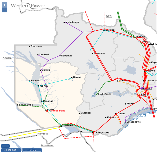
Power Evacuation
Existing Infrastructure: While there is already a 66kV powerline near our project site, it cannot handle all the power we’ll generate.
New Powerline Construction: To efficiently transmit our generated power, we’ll build a new 330kV powerline to the Sesheke substation. This will be part of the planned grid extension north to Lukulu.
Collaborative Effort: ZESCO has entrusted Western Power Company (WPC) with the construction of this 110km transmission line, which will be included in the EPC contract.
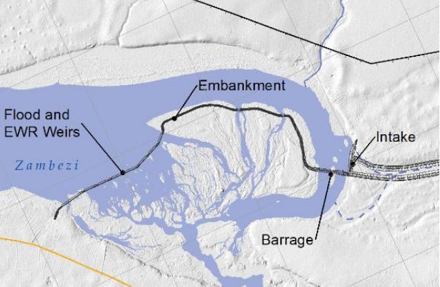
Headworks
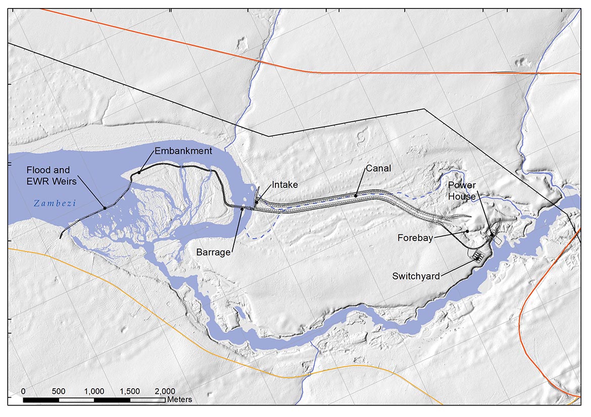
Our innovative headworks system is a marvel of engineering, designed to ensure optimal performance and environmental harmony. Here’s how it works:
Water Level Management: Our series of weirs, embankments, and a concrete barrage maintain a steady water level of 990 meters above sea level upstream of the power station.
Flood Control: Adjustable crest-level weirs can be lowered to manage flood flows, preventing significant upstream flooding.
Environmental Stewardship: Weirs are in place to consistently meet Environmental Flow Requirements, preserving the local ecology and habitat between the weir and the powerhouse.
Fish-Friendly Design: Special fish passages allow aquatic life to move freely up and downstream, ensuring the ecosystem remains vibrant.
By diverting a portion of the river’s flow through our intake structure and into the power canal, we harness the river’s energy efficiently and sustainably.
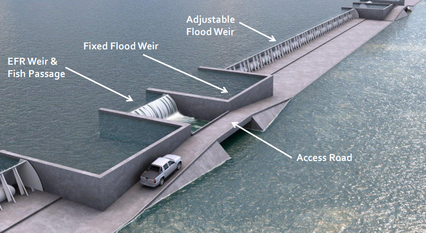
Our headworks on the west (right) river channel are designed with both efficiency and environmental care in mind.
Constant Water Flow: Our adjustable Environmental Flow Requirement (EFR) weirs ensure a steady flow of water, maintaining ecological balance.
Fish Migration: Equipped with multiple fish ladders, our infrastructure allows fish to migrate freely past the power station, supporting local biodiversity.
Flood Management: The adjustable weirs can be raised or lowered to control water flow, adapting to varying conditions.
Easy Maintenance: An access road provides convenient maintenance for the adjustable weirs, ensuring smooth operation.
By integrating these features, we harness the river’s power while preserving its natural beauty and ecological health.
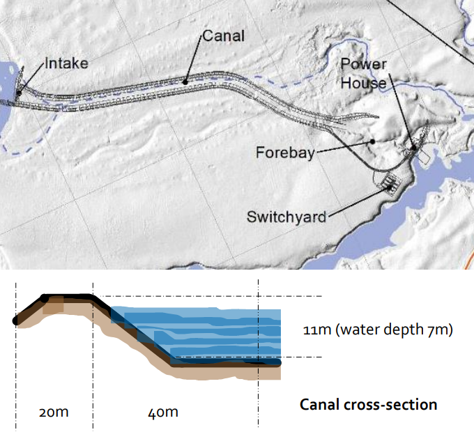
Canal and Forebay
Our power canal is a key component in our energy generation process.
Efficient Water Transport: The power canal stretches 3km from the headworks and intake to the powerhouse, where electricity is generated.
Robust Design: With a depth of 11 meters and a maximum water depth of 7 meters, the canal can handle a flow of 1,100 cubic meters per second.
Spacious Structure: Including its retaining embankments and access roads, the canal spans about 120 meters in width.
Engineered for Durability: Partially excavated into the terrain and lined with concrete, the canal is built to last.
Forebay Buffer: At the canal’s end, a forebay formed from the natural landscape and retaining dams holds a buffer of water, ensuring a constant flow through the turbines
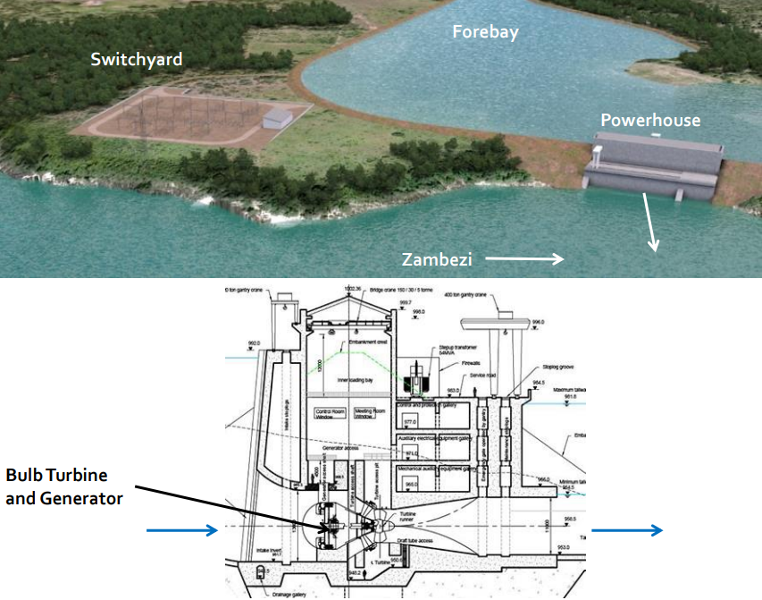
Powerhouse &
Switchyard
Our powerhouse is the heart of our energy generation, featuring the below technology and design:
Powerful Turbines: Inside the powerhouse, you’ll find four identical 45MW bulb turbines. These turbines, driven by the force of water, generate our electricity.
Operational Hub: The powerhouse also houses all the maintenance and control equipment necessary to keep the power station running smoothly.
Seamless Integration: The electricity produced is sent to the switchyard, where the voltage is boosted to 220kV for transmission and connected to the national grid.
Discreet Design: Standing nearly 60 meters tall, most of the powerhouse is cleverly excavated into the riverbank, making it unobtrusive and preserving the natural landscape.